Modern chip design differs to conventional software engineering in three fundamental aspects that require a somewhat different approach to project development:
-
Transformations and representations. The creation of a chip design from a source-level representation through to a final GDSII description of the layout involves many stages of incremental transformations of the circuit and layout, and then incremental assembly of components into various subsystems before finally the entire chip. At various stages through this process, checks are performed on the design typically using simplified representations to reduce complexity and make run times practical.
-
Tooling. Compared to software tooling, standard chip-design tooling (known in the industry as electronic design automation) : (1) is almost all proprietary and used under license, meaning that interactive and automated use is limited and at odds with a continuous-integration model of development; (2) can have long run times (upwards of 12 hours for a job are not uncommon) and produce vast quantities of data, making it very unattractive to rerun something unless absolutely necessary; and (3) can be non-deterministic in that rerunning a job with the same set of inputs produces a different output.
-
Tape out. When a design is released for manufacture (known in the industry as a tape out), there are typically high non-recoverable expenses associated with setting up the processes and a long lead time in receiving a (hopefully) working device. There are two implications of this situation: (1) chip tape outs precludes incremental releases, for example to fix trivial bugs, and therefore means that the confidence in the correct functionality of the design must be very high; (2) post tape out, the design source code is effectively frozen forever more for the purposes of debug and analysis.
Despite these differences, many of the techniques and tools from software engineering can readily be applied to chip development, particularly to manage complexity and maintain high standards of code quality, testing and integration. This note lays out some thoughts and opinions on the components and structure of a software infrastructure to build chips.
Table of contents
Aims
The overall objective of a silicon infrastructure is to support the development of a verified chip design from RTL to GDSII. To make this more specific, I also define the following capabilities that should be supported as an overall philosophy of the approach that is explored in this note:
-
To rerun everything from scratch, requiring full automation of an the end-to-end flow. This is intended to: (1) distribute the task of integrating components of a design across a team, thereby revealing issues at as earlier stage in the project as possible to avoid disruptive changes towards the end; (2) enable faster design iteration; and (3) provide traceability of results (a foundation for the next aim).
-
Provide a full audit trail such that a release of a design for tape out has data and a set of reports, logs, coverage metrics, documentation and signoffs that are traceable back to the original RTL source files. This is important for building confidence to tape out, as well as providing information for future work on a completed design.
-
Support multiple chips and frozen designs to keep previous generations alive for debug of silicon issues and/or as a basis for a incremental tape out (known as a respin), and to allow multiple designs to be built concurrently.
Guiding principles
I think it is useful to underpin the aims, implementation and operation of a chip-design infrastructure are a set of guiding principles for the project team to employ when design decisions need to be made. These principles are formed from my own experience and through conversations with others. I am sure that alternative foundations can be constructed and argued for.
-
Simple and explicit. Build a complex system using simple, well-defined components composed and controlled using explicit mechanisms. Conversely, avoid easy-to-use high-level interfaces that hide important behaviours. This borrows from the Zen of Python: explicit is better than implicit and simple is better than complex. Examples include avoiding the use of global variables, preferring flat rather than nested, preferring decisions to be made explicitly and avoiding special cases that break the rules.
-
Use a monorepository. One repository should contain all the code for all active projects. This enhances all team members’ ability to integrate their changes across projects and removes barriers to interaction between different teams and/or areas of the design. Other general benefits of a monorepository are the ability to reuse code and do large-scale refactoring. A great deal of care must be taken to manage dependencies between projects/components within a monorepository. Without such care, unexpected interdependencies can cause unexpected breakages, prevent refactoring and preclude focused testing. In general: isolate components by restricting them to only be able to access their listed dependencies; divide components by function and abstraction level (eg don’t group by language or technology); and use a standard structure for each component (such as
lib,sources,READMEetc). -
Embrace open source. To save on effort, leverage freely-available tools and libraries wherever possible in the infrastructure, rather than implementing custom versions. Where open source is used, contributions back upstream benefit the community and help to align the project with the way it is being deployed. This particularly applies to open source in the ASIC/FPGA domain, where open-source software is unencumbered by licensing restrictions. Often chip projects will be on tight schedules, so careful judgment of the effort-benefit tradeoff must be made.
-
Performance is important. With the ability to rerun everything from scratch coupled with a multi-chip and monorepository approach, the compute demands can scale quickly so it is crucial that the infrastructure is performant. This can easily become a problem with codebases make extensive use of a scripting language such as Python. Mitigations include writing (or rewriting) parts in a lower-level language such as C++, and setting things up in such a way that this Python and C++ components can interoperate cleanly (eg well-defined boundaries and dependencies).
Flows
This section outlines the high-level flows that a chip-design infrastructure needs to support, meaning (typically) a sequence of steps to achieve some task. This is not meant to be exhaustive, but characteristic of the types of tasks that need to be performed. Flows can be just a single step or can be composed together to create different flows, but always have defined inputs and outputs. I use the term job to mean a particular program or script that is executed, typically corresponding to a step.
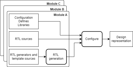
- Design representation. To read a design into a tool, the design must have a complete representation including tool-agnostic configuration, macro defines, library files and RTL sources. Often, RTL code will need to be generated programatically using templates or other types of code generators. It is also typical that a design will be implemented in a hierarchical fashion, so a configuration step must gather together the required modules and package it into a single representation. As an example, the open-source Bender dependency management tool provides very similar functionality.
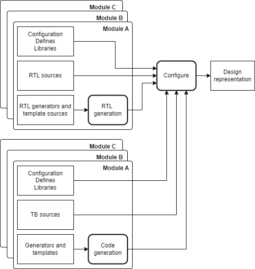
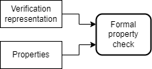
- Verification representation. For the purposes of simulation and analysis, a verification representation is a variation of a design representation, adding configuration and macro defines, source files for a test bench, monitors, assertions etc, and possibly substituting parts of the design for fast models or block boxes. These verification components will likely live with the corresponding parts of the design and be collected together as they were for the design representation during a configuration step.
- Lint checking. RTL source code can be checked for basic coding issues (referred to as linting) by passing it through tools that perform various built-in or custom checks. The input to this task is the specification of a design and the output is a list of warnings to be reviewed. Example open-source tools that can be used for linting are Verilator, Verible, Slang, svlint and Yosys.

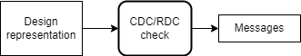
- CDC and RDC checking. Clock- and reset-domain crossings can be checked automatically with tools that analyse a design, typically with a set of annotations and constraints. The output will be warning messages from the checker that need to be investigated.
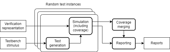
- Simulation testbench. A simulation test bench requires a representation of the design, a verification environment and test stimulus. Test stimulus is often randomly generated. Coverage (structural or functional) can be collected during simulation and when many test instances are run for a particular test generator or over a larger regression of different test generators, coverage may need to be merged then reported on. Simulation is typically performed on an RTL representation, but can also be performed on gate-level netlists and with and without delay annotations.
- Formal property test bench. Analysing and proving formal properties of a design is a complementary technique to standard functional coverage. Inputs to this are a verification representation of the design and a set of assumptions and properties to be checked.
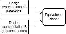
- Formal equivalence check. As a design is incrementally transformed between RTL and GDSII, it is essential to perform equivalence checks to prove that each transformation maintains the functional behaviour of the design. Inputs to an equivalence check are two representations, typically called a reference that is the baseline and an implementation to check.
- Physical build. All flows up to this point have mainly operated on RTL representations of a design. A physical build flow starts off by transforming RTL into gates using a synthesis tool, then progressively transforming the design into a set of two-dimensional layers. Following synthesis are: scan insertion for DFT, floorplanning (placing ports and macros), placement (placing cells), clock tree synthesis, routing (establishing all required connections using the available routing layers, finishing and checking. See OpenROAD for an example open source physical build flow.

A note on DFT. A central aspect of any chip design is the DFT (device test) strategy. Testability is achieved by adding logic in the form of instruments and connectivity to make the the existing logic controllable and observable. The means by which this is done and the point in the development process is heavily dependent on the design and the tooling used. Typically, DFT logic is inserted using automated tools during the physical build but increasingly it is being added in RTL also using automated tooling - either way adding additional transformation steps to the front- or back-end flows.
A note on physical builds. There are two unique aspects of physical builds that present challenges for the infrastructure presented in this note. The first is that physical EDA tools do not always produce the same output given the same inputs due to the nature of the optimisation algorithms they use. The second is that close to the closure of a design component, manual interventions will be made to address localised issues in the design. The combination of these issues mean that it is not possible to rerun physical builds from scratch and achieve satisfactory results. Therefore, a silicon infrastructure must be able to support frozen data from particular flow stages.
Model
A model for a silicon infrastructure that captures the use cases described is a hierarchical collection of tasks that consume inputs and produce outputs. A task can be dependent on another task by consuming that task’s output and tasks can be composed together in this way into flows. The set of tasks implementing a flow form an acyclic directed graph (DAG) with nodes representing fixed inputs or jobs and edges corresponding to dependencies. The structure of this graph is determined statically (ie without any dependence on runtime data). Execution proceeds by running tasks whose inputs are ready and letting the task run to completion before marking its outputs as available to trigger the execution of more tasks or the termination of the flow.
A task is defined by:
- A set of inputs.
- A set of outputs.
- A set of configuration values.
- A set of resource requirements (time, memory, cores).
- An action that that operates only on the inputs and must produce all the of the outputs, typically achieved by executing a script or separate tool.
- If a task attempts to access an input that is not specified, then an error is raised.
A flow is a hierarchical task and defined by:
- A set of inputs.
- A set of outputs.
- A set of configuration values.
- A set of resource requirements.
- A action consisting of executing one or more tasks according to their dependencies. Inputs and outputs of the flow must be connected to the sub tasks and similarly for dependencies between sub tasks.
- Tasks can be specified using replication with static bounds to create arrays, and conditionality to include or exclude tasks dependent on configuration values.
Configuration values are used to control the behaviour of a flow or task. A flow can propagate configuration into its sub tasks, but it must do so explicitly. Configuration values can be set on the command line. Example use of configuration options is to control features like debug flags, substitution of components of the design for simulation, or the inclusion of tests to run in a regression.
There are a number of similar programming models that support scalable pipelined data processing. In the field of genomics, the Workflow Description Language (WDL) and Common Workflow Language (CWL) are open programming language specifications. Example implementations of WDL are MiniWDL and Cromwell, and of CWL are cwltool and Toil. A Nextflow offers comparable features but is based on a domain-specific language implemented in Groovy. This paper offers a good comparison of WDL, CWL and Nextflow. Also worth mentioning are Snakemake, Apache Airflow, Apache Beam, Luigi and Flyte. I’m still investigating the suitability of these tools for Silicon design workloads.
Implementation details
This section records some important details to consider when implementing a silicon flow, as well as some nice-to-have features.
-
Environment. A controlled environment execution environment with specific tool versions for reproducability and legacy support. Container technology supports this requirement very will with implementations such as Singularity/Apptainer. A lighter-weight solution is faketree for managing filesystem layout in a dynamic way to meet the constraints of EDA tools.
-
Access to compute. Dispatching of jobs to compute resources such as a compute cluster requires interaction with a queuing system such as Slurm.
-
Logging. Extensive logging of job statuses is important for a compute-intensive workload. Straightforward access to these logs for inspection during and after the run should be provided, likely through a web-based dashboard.
-
Fault tolerance. Flows should be robust to failures. When an task failure does occur, the correct statuses should be propagated up any hierarchy of tasks to provides visibility of the issue. The logging infrastructure should record any progress that was made, providing a starting point for debug or to restart the task. It should be straightforward to rerun part of a job that has failed in a reproducible way.
-
Storage. The use of a shared filesystem such as NFS is typical in silicon EDA flows, however it creates a single point of failure and has limited scalability. An alternative shared storage system is object storage such as MinIO.
-
Releasing. It should be simple to release data from the repository into immutable storage that can then be referenced as a dependency.
-
Periodic jobs. A mechanism for running periodic jobs is required to implement a continuous-integration (CI) and/or continuous-delivery (CD). Jenkins, GitHub Actions or GitLab CI/CD are all directly applicable here.
Summary
This note outlines the principles and requirements for a modern software infrastructure to build chips. This is very different to conventional software engineering due to fundamental differences in processes, and is likely to be quite different from the typical methodologies used in conventional silicon design. Based on some simple use cases, a model is proposed that abstracts the details of resource allocation and data movement by providing tasks with inputs and outputs as primitives. Surprisingly, there already exist a family of tools from data science that employ a very similar model.
Acknowledgments
The motivation for writing this note came from recent discussions on building a from-scratch silicon infrastructure with James Pallister and Peter Birch. This note is a synthesis of ideas from those conversations.
Related projects
- Gator, a framework for running a hierarchy of jobs and aggregating logs, metrics, resource utilisation, and artefacts.
- Blockwork, is a build system and orchestrator for silicon design.
- Blade is a tool for autogenerating modules, interconnects and register definitions from an YAML schema.
- Siliconcompiler is a modular build system for silicon hardware.
- Berkeley Chipyard is an agile framework for hardware design, using Chisel for RTL specification.
- Berkeley Hammer is a physical design framework.
- Pulp Platform Bender is a dependency management tool for hardware design projects.
- Rich Porter’s series on digital verification and source code for the project.
- Melding hardware and software: a story in the making, a position piece by Enfabrica on their approach to ASIC design.